
abs light on...


Joined: Apr 2010
Posts: 12,609
From: Mentor, Ohio

I lean back on what 03SSLE mentioned. I can get the troubleshooting guide for this error code (sorry I forgot to do it when I mentioned, I can try to pull it tomorrow).
Joined: Apr 2010
Posts: 12,609
From: Mentor, Ohio
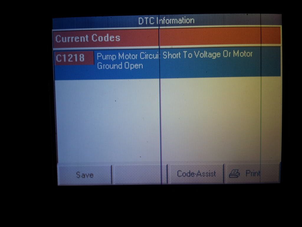
I hope this helps (the troubleshooting info from the shop book):
DTC C1218
Circuit Description
The system relay is energized when the ignition is ON. The system relay supplies voltage to the solenoid valves and the pump motor. This voltage is referred to as the system voltage.
The electronic brake control module (EBCM) controls each solenoid valve by grounding the solenoid.
The EBCM controls the pump motor by grounding the control circuit. The pump serves 2 purposes:
One of the following conditions exists for 0.16 seconds:
If equipped, the following actions occur:
The pump motor is integral to the BPMV. The pump motor is not serviceable.
Test Description
The number below refers to the step number on the diagnostic table.
</th><th rowspan="1" align="center" valign="bottom">Action
</th><th rowspan="1" align="center" valign="bottom">Yes
</th><th rowspan="1" align="center" valign="bottom">No
</th></tr> <tr> <td rowspan="1" colspan="4" align="left" valign="middle">Schematic Reference: Antilock Brake System Schematics
Connector End View Reference: Antilock Brake System Connector End Views
</td></tr> <tr> <td rowspan="1" align="center" valign="middle">1
</td><td rowspan="1" align="left" valign="top">Did you perform the ABS Diagnostic System Check?
</td><td rowspan="1" align="center" valign="bottom">Go to Step 2
</td><td rowspan="1" align="center" valign="bottom">Go to Diagnostic System Check - ABS
</td></tr> <tr> <td rowspan="1" align="center" valign="middle">2
</td><td rowspan="1" align="left" valign="top">
</td><td rowspan="1" align="center" valign="bottom">Go to Step 3
</td><td rowspan="1" align="center" valign="bottom">Go to Testing for Intermittent Conditions and Poor Connections in Wiring Systems
</td></tr> <tr> <td rowspan="1" align="center" valign="middle">3
</td><td rowspan="1" align="left" valign="top">
</td><td rowspan="1" align="center" valign="bottom">Go to Step 5
</td><td rowspan="1" align="center" valign="bottom">Go to Step 4
</td></tr> <tr> <td rowspan="1" align="center" valign="middle">4
</td><td rowspan="1" align="left" valign="top">
</td><td rowspan="1" align="center" valign="bottom">Go to Step 9
</td><td rowspan="1" align="center" valign="bottom">--
</td></tr> <tr> <td rowspan="1" align="center" valign="middle"> 5
</td><td rowspan="1" align="left" valign="top">
</td><td rowspan="1" align="center" valign="bottom">Go to Step 8
</td><td rowspan="1" align="center" valign="bottom">Go to Step 6
</td></tr> <tr> <td rowspan="1" align="center" valign="middle">6
</td><td rowspan="1" align="left" valign="top">
</td><td rowspan="1" align="center" valign="bottom">Go to Step 9
</td><td rowspan="1" align="center" valign="bottom">Go to Step 7
</td></tr> <tr> <td rowspan="1" align="center" valign="middle">7
</td><td rowspan="1" align="left" valign="top">Replace the EBCM. Refer to Electronic Brake Control Module Replacement .
Did you complete the repair?
</td><td rowspan="1" align="center" valign="bottom">Go to Step 9
</td><td rowspan="1" align="center" valign="bottom">--
</td></tr> <tr> <td rowspan="1" align="center" valign="middle">8
</td><td rowspan="1" align="left" valign="top">Replace the BPMV. Refer to Brake Pressure Modulator Valve Replacement .
Did you complete the repair?
</td><td rowspan="1" align="center" valign="bottom">Go to Step 9
</td><td rowspan="1" align="center" valign="bottom">--
</td></tr> <tr> <td rowspan="1" align="center" valign="middle">9
</td><td rowspan="1" align="left" valign="top">
</td><td rowspan="1" align="center" valign="bottom">Go to Step 2
</td><td rowspan="1" align="center" valign="bottom">System OK
</td></tr></tbody></table>
DTC C1218
Circuit Description
The system relay is energized when the ignition is ON. The system relay supplies voltage to the solenoid valves and the pump motor. This voltage is referred to as the system voltage.
The electronic brake control module (EBCM) controls each solenoid valve by grounding the solenoid.
The EBCM controls the pump motor by grounding the control circuit. The pump serves 2 purposes:
<table border="0"><tbody><tr><td valign="top"> � </td><td valign="top">Transfers brake fluid from the brake calipers to the master cylinder reservoir during pressure decrease events.</td></tr></tbody></table>
<table border="0"><tbody><tr><td valign="top"> � </td><td valign="top">Transfers brake fluid from the master cylinder reservoir to the brake calipers during pressure increase events.</td></tr></tbody></table>
Conditions for Running the DTC<table border="0"><tbody><tr><td valign="top"> � </td><td valign="top">The pump motor is commanded ON.</td></tr></tbody></table>
<table border="0"><tbody><tr><td valign="top"> � </td><td valign="top">The system voltage is greater than 8 volts.</td></tr></tbody></table>
Conditions for Setting the DTCOne of the following conditions exists for 0.16 seconds:
<table border="0"><tbody><tr><td valign="top"> � </td><td valign="top">With the commanded pump motor voltage less than the system voltage, the actual pump motor voltage is 3 volts less than the commanded voltage.</td></tr></tbody></table>
<table border="0"><tbody><tr><td valign="top"> � </td><td valign="top">With the commanded pump motor voltage greater than the system voltage, the actual pump motor voltage is less than 8 volts.</td></tr></tbody></table>
Action Taken When the DTC SetsIf equipped, the following actions occur:
<table border="0"><tbody><tr><td valign="top"> � </td><td valign="top">The EBCM disables the ABS/TCS for the duration of the ignition cycle.</td></tr></tbody></table>
<table border="0"><tbody><tr><td valign="top"> � </td><td valign="top">The DRP does not function optimally.</td></tr></tbody></table>
<table border="0"><tbody><tr><td valign="top"> � </td><td valign="top">The ABS indicator turns ON.</td></tr></tbody></table>
<table border="0"><tbody><tr><td valign="top"> � </td><td valign="top">The Traction Off indicator turns ON.</td></tr></tbody></table>
<table border="0"><tbody><tr><td valign="top"> � </td><td valign="top">The message center displays the Service Traction System message.</td></tr></tbody></table>
Conditions for Clearing the DTC<table border="0"><tbody><tr><td valign="top"> � </td><td valign="top">The condition for the DTC is no longer present and the DTC is cleared with a scan tool.</td></tr></tbody></table>
<table border="0"><tbody><tr><td valign="top"> � </td><td valign="top">The electronic brake control module (EBCM) automatically clears the history DTC when a current DTC is not detected in 100 consecutive drive cycles.</td></tr></tbody></table>
Diagnostic AidsThe pump motor is integral to the BPMV. The pump motor is not serviceable.
Test Description
The number below refers to the step number on the diagnostic table.
- Tests the ability of the EBCM to control the pump motor. If the test lamp illuminates, the pump motor circuit within the EBCM is good.
</th><th rowspan="1" align="center" valign="bottom">Action
</th><th rowspan="1" align="center" valign="bottom">Yes
</th><th rowspan="1" align="center" valign="bottom">No
</th></tr> <tr> <td rowspan="1" colspan="4" align="left" valign="middle">Schematic Reference: Antilock Brake System Schematics
Connector End View Reference: Antilock Brake System Connector End Views
</td></tr> <tr> <td rowspan="1" align="center" valign="middle">1
</td><td rowspan="1" align="left" valign="top">Did you perform the ABS Diagnostic System Check?
</td><td rowspan="1" align="center" valign="bottom">Go to Step 2
</td><td rowspan="1" align="center" valign="bottom">Go to Diagnostic System Check - ABS
</td></tr> <tr> <td rowspan="1" align="center" valign="middle">2
</td><td rowspan="1" align="left" valign="top">
- Use the scan tool in order to clear the DTCs.
- With the scan tool, perform the Automated Test.
</td><td rowspan="1" align="center" valign="bottom">Go to Step 3
</td><td rowspan="1" align="center" valign="bottom">Go to Testing for Intermittent Conditions and Poor Connections in Wiring Systems
</td></tr> <tr> <td rowspan="1" align="center" valign="middle">3
</td><td rowspan="1" align="left" valign="top">
- Turn the ignition OFF.
- Remove the EBCM from the BPMV. Refer to Electronic Brake Control Module Replacement .
- Inspect the EBCM to BPMV connector for conditions which could cause an intermittent, such as damage, corrosion, poor terminal contact, or presence of brake fluid.
</td><td rowspan="1" align="center" valign="bottom">Go to Step 5
</td><td rowspan="1" align="center" valign="bottom">Go to Step 4
</td></tr> <tr> <td rowspan="1" align="center" valign="middle">4
</td><td rowspan="1" align="left" valign="top">
- If connector corrosion or damage is evident, replace BPMV and/or EBCM as necessary.
- If brake fluid is present, replace both BPMV and EBCM. Refer to Brake Pressure Modulator Valve Replacement and Electronic Brake Control Module Replacement .
</td><td rowspan="1" align="center" valign="bottom">Go to Step 9
</td><td rowspan="1" align="center" valign="bottom">--
</td></tr> <tr> <td rowspan="1" align="center" valign="middle"> 5
</td><td rowspan="1" align="left" valign="top">
- Connect the EBCM harness to the EBCM with the BPMV still separated.
- Connect a test lamp between the pump motor circuits, internal EBCM side, using the J 35616 Connector Test Adapter Kit .
- Turn the ignition ON.
- With the scan tool, perform the Automated Bleed.
</td><td rowspan="1" align="center" valign="bottom">Go to Step 8
</td><td rowspan="1" align="center" valign="bottom">Go to Step 6
</td></tr> <tr> <td rowspan="1" align="center" valign="middle">6
</td><td rowspan="1" align="left" valign="top">
- Turn OFF the ignition.Important: Removing battery voltage or ground from the EBCM will result in the following conditions:
<table border="0"><tbody><tr><td valign="top"> � </td><td valign="top">Loss of the TIM learned tire inflation configuration parameters in the EBCM</td></tr></tbody></table><table border="0"><tbody><tr><td valign="top"> � </td><td valign="top">The EBCM sets DTC C1245</td></tr></tbody></table>When the diagnosis is complete, inspect the tire pressures and perform the TIM reset. Refer to Tire Pressure Monitor Procedure in Tire Pressure Monitoring. - Disconnect the EBCM connector.
- Connect the J 39700 universal pinout box using the J 39700-99 cable adapter to the EBCM harness connector only.
- Test both ground circuits of the EBCM including the EBCM ground for a high resistance or an open. Refer to Circuit Testing and Wiring Repairs in Wiring Systems.
</td><td rowspan="1" align="center" valign="bottom">Go to Step 9
</td><td rowspan="1" align="center" valign="bottom">Go to Step 7
</td></tr> <tr> <td rowspan="1" align="center" valign="middle">7
</td><td rowspan="1" align="left" valign="top">Replace the EBCM. Refer to Electronic Brake Control Module Replacement .
Did you complete the repair?
</td><td rowspan="1" align="center" valign="bottom">Go to Step 9
</td><td rowspan="1" align="center" valign="bottom">--
</td></tr> <tr> <td rowspan="1" align="center" valign="middle">8
</td><td rowspan="1" align="left" valign="top">Replace the BPMV. Refer to Brake Pressure Modulator Valve Replacement .
Did you complete the repair?
</td><td rowspan="1" align="center" valign="bottom">Go to Step 9
</td><td rowspan="1" align="center" valign="bottom">--
</td></tr> <tr> <td rowspan="1" align="center" valign="middle">9
</td><td rowspan="1" align="left" valign="top">
- Use the scan tool in order to clear the DTCs.
- With the scan tool, perform the Automated Test.
</td><td rowspan="1" align="center" valign="bottom">Go to Step 2
</td><td rowspan="1" align="center" valign="bottom">System OK
</td></tr></tbody></table>

Thread
Thread Starter
Forum
Replies
Last Post
hotrodharley
Monte Carlo Repair Help
2
Nov 15, 2013 11:37 AM
thomasnchy
Monte Carlo Repair Help
2
Jun 5, 2008 08:23 PM