
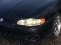
What is the I/O button next to headlight switch?
#11
 03-04-2017 | 02:39 PM

Thread Starter

Joined: Dec 2016
Posts: 22

Thanks for the replies, which steered me to the answer. You guys were right. It turns out the switch was aftermarket and turns off/on front sonar sensors we added with backup camera last year. I never put it together because the sensors were not activated when I was testing the button. Sorry for the lame post, which I should have figured out earlier. My next one regarding the rear view mirror wires and easiest way to fix wires affecting the compass/temperature, autodim and map lights may be better (intermittent and work for awhile while moving wires). Thanks
#12
03-04-2017 | 04:33 PM
Joined: Feb 2017
Posts: 114

Sadly the Autodim Mirror seems to be a week link in the Soldering connections. Not always have I seen this. More often then the Mirror leak. Only way to fix this is just as hard as replacing the mirror glass.
Taking the Mirror down by loosening the set screw, turn mirror around so you can see the connector and push in the clip pull out connector. Then with out damaging the case using a hard tool and separate the front and back half. This will be somewhat difficult because the Mirror is covered in Double Backed Sticky Tape the whole length of the mirror. Once apart, You will need to remove the Board from the white sticky tape. The reason is because the solder area is on the other side of the plug in area. This isn't very easy but can be done. You will want to be careful because you don't want to crack the mirror.
If you damage the Mirror it will leak and it won't work as Auto Dim anymore and the glass over a few days will not look the same. Reason is because there is a Liquid that is sealed in between glass and mirror, This is giving a charge and that is how the dimming works.
Anyway once you have the PCB off the Double sided tape, Take some 99% ALCOHOL and clean up the solder joints if needed. If not really needing much cleaning use some No clean Electrical Flux and to help with flow of solder use some 60/40 or 63/37 leaded solder and add some to the Non leaded soldered joint. Then you can Re flow the connections for the connector. Once all the pins are nice new and set. Clean up the soldered area to remove the flux.
If you know someone in Electronics Repair, Use their Ultrasonic Cleaner station, then Alcohol bath and a dryer set up. (Some people use a Toaster oven to aid in drying). Once all clean and ready to install back into the Housing, Line it up with the area on the double sided sticky tape, It should still be sticky if you didn't have it in an area full of dust while working on the board. Connect the Mirror Glass wires back to it and use some fast set CA. I have used the Insta Set Accelerator to help with fast bonding. Just keep the CA in an area that can't be seen when the 2 parts are put together.
If not sure about the Reflow, I would test the Mirror and lights before CA bond part is started. This way you don't have to take it apart again.
James