
2001 MC SS Fuel Problem!


Old thread, I know... I just want to say that this was an easy DIY. Dont try and skip the step when you have to relieve the pressure. I skipped over it and removed one of the lines and had gas sprayed all over my face and body and ended up with the hose pipe in my face for 15 minutes... Just a reminder to do every step as listed!!!

thank god for this thread i was about to get my fuel pump replaced tomorrow when i get paid now i just found out i can get this sensor and DIY... this will be my first project on my car and im extremely nervous but hopefully it all works out


Joined: Sep 2011
Posts: 6
From: QUEENS,N.Y.
01 2001 Chevrolet Monte Carlo Fuel Pump - Fuel Delivery - Delphi, Airtex, Denso - PartsGeek
GOOD SOURCE FOR FUEL RELATED PARTS
GOOD SOURCE FOR FUEL RELATED PARTS


@ StrongTakeover: thank god for this thread i was about to get my fuel pump replaced tomorrow when i get paid now i just found out i can get this sensor and DIY... this will be my first project on my car and im extremely nervous but hopefully it all works out
Trust me, don't be nervous while trying to repair a fuel problem. We all can say its an easy fix but we was just like you (nervous). For the ones who DIY, like myself! Just have all your tools and the instructions on HOW TO DO and you can't go wrong. Confidence mannnnnnn!!!!!
Trust me, don't be nervous while trying to repair a fuel problem. We all can say its an easy fix but we was just like you (nervous). For the ones who DIY, like myself! Just have all your tools and the instructions on HOW TO DO and you can't go wrong. Confidence mannnnnnn!!!!!

I didn't mine last year and ordered the part of Internet for like 20.00 dollars and took me about 2 hours and it was very basic but I am very mechanically inclined but it s very basic great pics perfect but I think I got it off eBay not the fuel pump just the sensor ..The people I bought I got it from sell like 50 of them a month hope this help someone save money

Joined: Mar 2010
Posts: 364
I've been having the same issue as well... but has anyone noted that you can turn your car's ignition repeatedly to the off and on, and as the fuel gauge sweeps, it will go back to it's original position? I usually turn the ignition to the on position then off around 5-7 times... but never actually starting the car. I do this and it gives me a good couple of weeks without issue... maybe longer. But eventually, the unit will need replacing.

Joined: Jun 2012
Posts: 5
From: Huntsville Al.
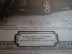
This procedure for fuel pump module or fuel level sensor replacement applies only to 2000-2004 Monte Carlo's. By the way,the driver information center in the overhead console relies on data from the fuel level sensor along with several other data inputs to make it's fuel information calculations.If the fuel level sensor data is skewed the driver information center display will be inaccurate. The artwork depicting the location of the access panel under the trunk carpet is rather poor,but the location is very obvious once the carpet is removed.
[hr]
Fuel Sender Assembly Replacement [/align]
Removal Procedure
Caution:Fuel Vapors can collect while servicing fuel system parts in enclosed areas such as a trunk. To reduce the risk of fire and increased exposure to vapors: [align=left]
�€�
Use forced air ventilation such as a fan set outside of the trunk.[/align][align=left]
�€�
Plug or cap any fuel system openings in order to reduce fuel vapor formation.[/align][align=left]
�€�
Clean up any spilled fuel immediately.[/align][align=left]
�€�
Avoid sparks and any source of ignition.[/align][align=left]
�€�
Use signs to alert others in the work area that fuel system work is in process.[/align]
Notice:Clean all of the following areas before performing any disconnections in order to avoid possible contamination in the system: [align=left]
�€�
The fuel pipe connections[/align][align=left]
�€�
The hose connections[/align][align=left]
�€�
The areas surrounding the connections[/align]
Important:For rear compartment (trunk) accessible fuel sender assemblies, completely remove the rear compartment carpet before removing the fuel sender access panel.
Important:Always replace the fuel sender O-rings when reinstalling the fuel sender assembly.
Important:The modular fuel sender assembly will spring-up when the snap ring is removed.
Important:Always maintain cleanliness when servicing fuel system components.
[ol]


Relieve the fuel system fuel pressure. Refer to Fuel Pressure Relief .
Remove the rear compartment trim panel. Refer to Rear Compartment Trim Panel Replacement in Body Rear End.
Remove the fuel sender access panel nuts.
Remove the fuel sender access panel.
Disconnect the fuel tank pressure sensor electrical connector.
Disconnect the fuel sender electrical connector.
Clean the fuel pipes, and fuel sender assembly to prevent possible fuel contamination during removal.
Disconnect the quick-connect fittings at the fuel sender assembly. Refer to Plastic Collar Quick Connect Fitting Service .

Remove the fuel sender retaining ring.
Remove the modular fuel sender assembly.
Clean the fuel sender assembly O-ring sealing surfaces.
Inspect the fuel sender assembly O-ring sealing surfaces. [/ol]
Installation Procedure
[ol]
Notice:Always re-attach the fuel lines and fuel filter with all original type fasteners and hardware. Do not repair sections of fuel pipes.
Important:Care should be taken not to fold over or twist the fuel pump strainer when installing the fuel sender assembly, as this will restrict fuel flow. Also, assure that the fuel pump strainer does not block full travel of float arm.
Important:Ensure that the fuel sender assembly retaining snap ring is fully seated within the tab slots on the fuel tank.
Position the new fuel sender assembly O-ring on the fuel tank.
Install the fuel sender assembly into the fuel tank.
Install the fuel sender assembly retaining ring while holding the fuel sender assembly down.
Connect the fuel sender electrical connector.
Connect the fuel tank pressure sensor electrical connector.
Connect the quick-connect fittings at the fuel sender assembly. Refer to Plastic Collar Quick Connect Fitting Service .
Install the fuel filler cap.
Connect the negative battery cable. Refer to Battery Negative Cable Disconnection and Connection in Engine Electrical.
Inspect for leaks. [align=left]
9.1.
Turn ON the ignition for 2seconds.[/align][align=left]
9.2.
Turn OFF the ignition for 10seconds.[/align][align=left]
9.3.
Turn ON the ignition.[/align][align=left]
9.4.
Inspect for fuel leaks.[/align]
Install the fuel sender access panel.
Notice:Use the correct fastener in the correct location. Replacement fasteners must be the correct part number for that application. Fasteners requiring replacement or fasteners requiring the use of thread locking compound or sealant are identified in the service procedure. Do not use paints, lubricants, or corrosion inhibitors on fasteners or fastener joint surfaces unless specified. These coatings affect fastener torque and joint clamping force and may damage the fastener. Use the correct tightening sequence and specifications when installing fasteners in order to avoid damage to parts and systems.
Install the fuel sender access panel nuts.
Tighten
Tighten the nuts to 10N·m (89lbin).
Install the rear compartment trim panel. Refer to Rear Compartment Trim Panel Replacement in Body Rear End.[/ol][/align]
[hr]
Fuel Sender Assembly Replacement [/align]
Removal Procedure
Caution:Fuel Vapors can collect while servicing fuel system parts in enclosed areas such as a trunk. To reduce the risk of fire and increased exposure to vapors: [align=left]
�€�
Use forced air ventilation such as a fan set outside of the trunk.[/align][align=left]
�€�
Plug or cap any fuel system openings in order to reduce fuel vapor formation.[/align][align=left]
�€�
Clean up any spilled fuel immediately.[/align][align=left]
�€�
Avoid sparks and any source of ignition.[/align][align=left]
�€�
Use signs to alert others in the work area that fuel system work is in process.[/align]
Notice:Clean all of the following areas before performing any disconnections in order to avoid possible contamination in the system: [align=left]
�€�
The fuel pipe connections[/align][align=left]
�€�
The hose connections[/align][align=left]
�€�
The areas surrounding the connections[/align]
Important:For rear compartment (trunk) accessible fuel sender assemblies, completely remove the rear compartment carpet before removing the fuel sender access panel.
Important:Always replace the fuel sender O-rings when reinstalling the fuel sender assembly.
Important:The modular fuel sender assembly will spring-up when the snap ring is removed.
Important:Always maintain cleanliness when servicing fuel system components.
[ol]
Relieve the fuel system fuel pressure. Refer to Fuel Pressure Relief .
Remove the rear compartment trim panel. Refer to Rear Compartment Trim Panel Replacement in Body Rear End.
Remove the fuel sender access panel nuts.
Remove the fuel sender access panel.
Disconnect the fuel tank pressure sensor electrical connector.
Disconnect the fuel sender electrical connector.
Clean the fuel pipes, and fuel sender assembly to prevent possible fuel contamination during removal.
Disconnect the quick-connect fittings at the fuel sender assembly. Refer to Plastic Collar Quick Connect Fitting Service .
Remove the fuel sender retaining ring.
Remove the modular fuel sender assembly.
Clean the fuel sender assembly O-ring sealing surfaces.
Inspect the fuel sender assembly O-ring sealing surfaces. [/ol]
Installation Procedure
[ol]
Notice:Always re-attach the fuel lines and fuel filter with all original type fasteners and hardware. Do not repair sections of fuel pipes.
Important:Care should be taken not to fold over or twist the fuel pump strainer when installing the fuel sender assembly, as this will restrict fuel flow. Also, assure that the fuel pump strainer does not block full travel of float arm.
Important:Ensure that the fuel sender assembly retaining snap ring is fully seated within the tab slots on the fuel tank.
Position the new fuel sender assembly O-ring on the fuel tank.
Install the fuel sender assembly into the fuel tank.
Install the fuel sender assembly retaining ring while holding the fuel sender assembly down.
Connect the fuel sender electrical connector.
Connect the fuel tank pressure sensor electrical connector.
Connect the quick-connect fittings at the fuel sender assembly. Refer to Plastic Collar Quick Connect Fitting Service .
Install the fuel filler cap.
Connect the negative battery cable. Refer to Battery Negative Cable Disconnection and Connection in Engine Electrical.
Inspect for leaks. [align=left]
9.1.
Turn ON the ignition for 2seconds.[/align][align=left]
9.2.
Turn OFF the ignition for 10seconds.[/align][align=left]
9.3.
Turn ON the ignition.[/align][align=left]
9.4.
Inspect for fuel leaks.[/align]
Install the fuel sender access panel.
Notice:Use the correct fastener in the correct location. Replacement fasteners must be the correct part number for that application. Fasteners requiring replacement or fasteners requiring the use of thread locking compound or sealant are identified in the service procedure. Do not use paints, lubricants, or corrosion inhibitors on fasteners or fastener joint surfaces unless specified. These coatings affect fastener torque and joint clamping force and may damage the fastener. Use the correct tightening sequence and specifications when installing fasteners in order to avoid damage to parts and systems.
Install the fuel sender access panel nuts.
Tighten
Tighten the nuts to 10N·m (89lbin).
Install the rear compartment trim panel. Refer to Rear Compartment Trim Panel Replacement in Body Rear End.[/ol][/align]
Thanks again!
Allen
Last edited by rocketallen; Jun 30, 2012 at 01:56 PM. Reason: gramar correction