Service Offered: LED conversion for Instrument Cluster + Climate Control Unit


Thread Starter


Joined: Dec 2009
Posts: 163
From: Ontario, Canada

Hi everyone,
My name is George and I own a 2003 Monte Carlo SS which as of recently have taken on the challenge of removing/disassembling/desoldering and resoldering blue LEDS in every switch, control unit in the interior of my car. I am a registered Apprentice Technician here in Ontario and have the hands on experience to accomplish such a patient and highly skilled job with the benefit of adding flare and reliability to the interior of your Monte Carlo.
Are you tired of having to look at burnt out interior lights while your cruising around the city at night?
If so, I've got the solution for you:
I am offering my services to anyone who wishes to have an LED conversion done to either their Instrument Cluster or their Climate Control Unit. My main goal is to solder on a set of 14V LEDS w/ current limiting resistor encased in the LED (colour of your choice) to your cluster or climate control unit. If you wish to have any interior switches done as well, I will replace those as well at an additional charge.
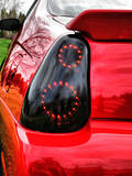
Below are a few examples of what your interior could look like after an LED conversion:
My name is George and I own a 2003 Monte Carlo SS which as of recently have taken on the challenge of removing/disassembling/desoldering and resoldering blue LEDS in every switch, control unit in the interior of my car. I am a registered Apprentice Technician here in Ontario and have the hands on experience to accomplish such a patient and highly skilled job with the benefit of adding flare and reliability to the interior of your Monte Carlo.
Are you tired of having to look at burnt out interior lights while your cruising around the city at night?
If so, I've got the solution for you:
I am offering my services to anyone who wishes to have an LED conversion done to either their Instrument Cluster or their Climate Control Unit. My main goal is to solder on a set of 14V LEDS w/ current limiting resistor encased in the LED (colour of your choice) to your cluster or climate control unit. If you wish to have any interior switches done as well, I will replace those as well at an additional charge.
Below are a few examples of what your interior could look like after an LED conversion:
Thread Starter
Joined: Dec 2009
Posts: 163
From: Ontario, Canada
I also offer Stepper Motor Services for anyone who has a faulty gauge with an inaccurate reading, non functioning and/or chattering gauges.
For anyone interested pricing is as follows:
(ALL PRICES INCLUDE PARTS & LABOUR. SHIPPING CHARGES ARE NOT INCLUDED WILL GET RATES THROUGH CANADA POST ONCE SHIPPING ADDRESS IS RECEIVED)
- Instrument Cluster (9 Bulb replacement) - $120 ... If you wish to have any stepper motors replaced re-re - $20 each motor
- Climate Control Unit (6 Bulb replacement) - $80
- Drivers + Passengers Side Door Switches (Windows/Door Locks/Side View Switch)/Heated Seat Switches/Fog Light/Trac OFF/Steering Wheel Controls - $20 (Each Switch)
- Dimmer/Interior Light Controller (2 Bulb Neo Wedge) - $40 (Price includes Disassembly + Parts. They are somewhat tricky to put back together)
Thank you all for looking,
*For anyone interested in having the radio bulbs replaced message first. Price will be roughly $120 for Radio*
PM requests open.
Cheers.
Last edited by l0gitech87; May 8, 2014 at 06:03 PM.


")
Thread Starter
Joined: Dec 2009
Posts: 163
From: Ontario, Canada
Red Monte... Sorry for the delay bro,
I just got back from work and did not have time to update my thread. The pictures that I was gonna upload are absolute s***. I don't have a good digital camera. I thought a 5MP camera would be okay for close ups but it did not come out as I expected it to be, the pictures were too damn blurry. I do apologize. The thing with these solder joints is they are way too small. The trick with soldering them perfectly and with precision is to heat up the existing joint and suck half of the solder off until you expose a small hole. You do not want to take or suck too much of the existing solder joint because than it will expose the silicone of the board and your hole will be too big and GOOD LUCK trying to get a solder joint to expand evenly on the board. They are very difficult to solder and really require patience and a steady hand. Too much heat and it could peel the trace off the wafer and thats not fun trying to fix. The joints themselves are literally half to 1MM apart from the next joint. If you solder them too close to the point they are touching it will short out the board entirely once you plug it back in to test. I'm not gonna lie, I killed my original board and had to purchase a new one in the dead of winter. I had no heat in my car for 2 days in -20degree C temperatures and that absolutely blows when you have to drive 30 min back and forth to work every morning. I am only telling you this based on mere experience. I felt really discouraged after destroying it and felt helpless to the point of shipping my stuff down to the states to have them done professionally. One other thing to keep in mind is polarity on the board. If you do not have a wiring diagram indicating where + and - are you will have to test the board alone and use a multimeter to find them. LED's work based on polarity, so if you solder them on the wrong way they will NOT light up. It takes practice/patience and some good knowledge of soldering to get this done properly and down to the tee. Let me know if you plan on doing this to your car yourself or if you wish to have it done by me. If you do plan on doing it yourself all I can say is all the best to you sir, it will be worth your while just like it was mine especially considering I am an apprentice tech. I will absolutely try my best and have at least 2 photos uploaded tomorrow of what the circuit board on the climate control unit looks like with the new LEDS with the digital camera we have at work.
Cheers man,
George